This is the second post about the iPCF protocol from Siemens. In the first one I described the working principle and operation modes. I also tried to show the difference between the iPCF and the PCF. In this topic I will go deeper into the iPCF packet format.
Below is the example of the iPCF communication. I used additional coloring rules to mark the iPCF frames in green.
According to pcap file, the Siemens iPCF use only six types of frames for communication:
iPCF frames
Common fields of i
PCF Frames
All iPCF frames have similar frame format:
- Frame control field. All subfields of the Frame Control field are same as in the standard Wi-Fi frame.
- Duration field. (Same meaning as in standard Wi-Fi)
- Receiver MAC Address (only one field)
- Frame body (except the ACK Frame)
- FCS
Actually, the format of the MAC header is very similar to the ACK Frame. The iPCF header has only one MAC address field.
S1G Beacon
The frame rate is about 30 frames per second. The number of tags in the payload is variable.
Unlike the S1G Beacon frame, the standard Beacon in the iPCF mode is broadcasted at one frame per second and has fixed tag fields.
According to the standard PCF protocol, the Beacon must announce the start of the Contention Free communication. In the iPCF neither the Beacon no S1G Beacon have information about the Contention Free time slot. In case an iPCF and a DCF wireless devices are sharing the same medium it can cause collisions.
Pool frame / Data Frame
As mentioned before, the Data Frame has the same format as the ACK frame, and it has the receiver address only.
The Frame has the Frame Type 3, and the Subtype 2.
Association Request
The Association Request has very simple MAC header with only one MAC field. It has also frame body, but the Wireshark cannot decode this information.
Below is the example of the Association iPCF Request Frame.
Association Response
Like all iPCF frames, the Association Response frame has very simple MAC header. As with an association request, the frame body of an association response cannot be decoded.
Below is the example of the Association Response Frame
Client Connection
You know that there are four mandatory steps if the wireless client what to connect to a BSSID.
- Active Probing (two-frame handshake)
- Authentication (two-frame handshake)
- 802.11 Association (two-frame handshake)
- Robust Security Network Association (RSNA) (at least four-frame handshake)
The iPCF use only the Association for client connection. The client sends an Association request, and the AP replies with the Association response. The transmitter confirms the successful receiving of an Association Frame with an ACK frame.
Client Roaming
The roaming procedure of the proprietary Siemens wireless LAN protocol is completely different.
In the standard Wi-Fi the wireless client uses the Reassociation Frame to inform the target access point about the previous connection. This information can be used to speed up authentication and receive buffered data packets from the first access point.
Siemens access points are standalone and the is not any cooperation protocol for exchanging information about clients.
The main thing, if we are talking about the roaming, is that it is always the client's decision. The trigger of the roaming depends on the Wi-Fi mode:
- In the iPCF mode the client stay connected to the first access point even the connection is bad. The client goes to the out-of-band passive scanning only if it loses the connection.
- In the iPCF-MC mode the client periodically goes to the MC channel for the passive scanning. If the signal strength of the neighbour access point is higher than the signal strength of the current access point, the client decides to roam. All access points in the iPCF-MC design have two radios in 5 GHz band.
- One for management communication (MC). All access points use the same MC channel
- Another one is for data communication (DC) is used for data plane.
So, in the iPCF mode the trigger for the roaming is the lost of the signal from the access point; in the iPCF-MC it is the signal level of Beacons on the MC channel.
Data / Pooling
Each client uses its timeslot for uplink and downlink communication with the access point.
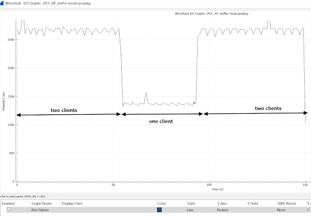
The following is an example of communication when two iPCF clients are connected to the same access point.
The I/O graph show us that each client uses about 1300 frames per second to communicate with the access point.
If we look at the Airtime graph below, we can see that each client requires about 8% of Airtime.
Conclusions
Traditionally let me summarise all information in a few key points.
- Not all in formation of iPCF frames can be decoded by standard Wi-Fi radio. This can course problems in mix operation of the iPCF and the DCF Wi-Fis. I recommend using different frequency domains for different systems.
- Use the iPCF mode for RCoax antennas only. Otherwise, it can course roaming issues.
- Take in account that the coverage of the MC channel should be the same or even a bit less than the coverage of the DC channel.
- Avoid DFS channels to protect your Wi-Fi from the radar interference.


